

Yodify Product Library
Add the Temperature Input Module for Zone 1 Series 9482/32 to your store or catalog
Book Your Demo and See How
or create your store
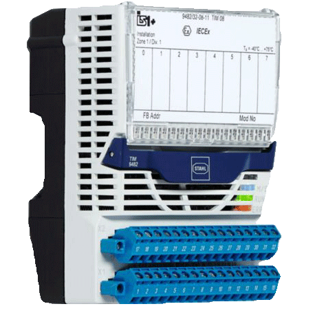
Temperature Input Module for Zone 1 Series 9482/32
Brand: R. STAHL AGThe series 9482 temperature input module for Zone 1 has eight channels for the Ex i operation of resistance temperature detectors with two-, three- or four-conductor connection and thermocouples.
Sensors that comply with DIN, IEC and GOST are supported as well as resistance transmitters up to 10 kΩ and also joysticks for rapid four-channel operation.
Earthed thermocouples can be connected.
Cold junction compensation can be performed internally or externally.
Features- Eight channels for resistance temperature detectors, potentiometers, thermocouples, mV sensors and joysticks
- intrinsically safe Ex ia inputs with line fault monitoring and LED error indication
- module in Zone 1 can be hot swapped
1 - 1 of 1 Part Numbers
217643
Eight channels for resistance temperature detectors, potentiometers, thermocouples, mV sensors and joysticks
intrinsically safe Ex ia inputs with line fault monitoring and LED error indication
module in Zone 1 can be hot swapped
Ambient Conditions
- Ambient temperature - -40°C ... +75°C
- Ambient temperature max. - +75°C
- Ambient temperature min. - -40°C
- Max. operating height - < 2000 m
- Max. relative humidity - 95% (without condensation)
- Note - (observe operating instructions)
- Storage temperature - -40°C ... +80°C
- storage temperature °C - -40 - 80 °C
- Storage temperature max. - +80°C
- Storage temperature min. - -40°C
Auxiliary power
- Auxiliary power Version - Intrin. safe Ex ia via BusRail
- Current consumption - 42 mA
- Max. power consumption - 1.00 W
- Max. power dissipation inputs - 1.0 W
- Power consumption max. - 1.00 W
- Power supply connection - BusRail types 9494
Device Specific Data
- AT_ST00265 - see table (connectable sensors)
- In. behaviour in case of error - hold last value
- Infl. of ambient temperature - 0,025 % / 10 K
- LED channel error - LED for each channel, red
- LED group error - "ERR" LED, red
- LED operating state - "RUN" LED, green
- LEDmodule requires maintenance - "M/S" LED, blue
- Line fault monitoring - OFF ON
- Module diagnostics message - OFF ON
- Module status and alarms - Internal bus error primer / redundant No response from IOM Configuration does not correspond to the module Hardware error Excess temperature Slot error Module requires maintenance
- operating mode - 4 channel fast (joystick) 8 channel precise
- Ref. junction compensation - internal (adjust. parameters) external 3-wire circuit
- Retrievable parameters - hardware revision manufacturer serial number software revision type
- Short circuit input - resist. transmitter < 15 Ω resist. temp. detec. < 15 Ω
- Signal status bit - 1 = Signal valid 0 = Signal interrupted
- Type external reference - PT1000 PT100 GOST PT100
- Type of connection - 2-, 3- and 4-wire circuits
- Wire breakage input - thermocouple > 1000 Ω resist. transmitter > 100 Ω resist. temp. detec. > 100 Ω mV sensor > 1000 Ω
Electrical Data
- Measuring range - shortfall exceeding
- Number of channels - 8 or 4 Ex i inputs (depending on operation mode)
Explosion Protection
- Ambient temperature °C - -40 - 75 °C
- Application range (Zone) Note - A suitable enclosure in accordance with the area of application must be used. Refer to the operating instructions.
- Application range (zones) - 1, 2, 21, 22
- ATEX dust certificate - DEKRA 13 ATEX 0140 X
- ATEX gas certificate - DEKRA 13 ATEX 0140 X
- Certificates - ATEX (DEK), Brazil (ULB), Canada (FM), EAC (STV), IECEx (DEK), Korea (KTL), Russia (Meteorological certificate), USA (FM)
- Dust explosion protection ATEX - II (1) D [Ex ia Da] IIIC
- Dust explosion protection IECEx - [Ex ia Da] IIIC
- Ex interface zone - 0, 1, 2, 20, 21, 22
- Gas explosion protection ATEX - II 2 (1) G Ex ia [ia Ga] IIC T4 Gb
- Gas explosion protection IECEx - Ex ia [ia Ga] IIC T4 Gb
- IECEX dust certificate - IECEx DEK 13.0046X
- IECEX gas certificate - IECEx DEK 13.0046X
- Installation - Zones 1, 2, 21, 22 and in the safe area
- Ship approval - ABS, CCS, ClassNK, DNVGL, RINA
Galvanic isolation
- Aux. power/system components - ≥ 1500 V AC
- I/O channels / ground (PA) - ≥ 500 V AC
- I/O channels/system components - ≥ 500 V AC
- I/O module / I/O module - ≥ 500 V AC
- Test volt. for gal. separation - acc. to standard EN 60079-11
General
- Functional Description - The series 9482 temperature input module for Zone 1 has eight channels for the Ex i operation of resistance temperature detectors with two-, three- or four-conductor connection and thermocouples. Sensors that comply with DIN, IEC and GOST are supported as well as resistance transmitters up to 10 kΩ and also joysticks for rapid four-channel operation. Earthed thermocouples can be connected. Cold junction compensation can be performed internally or externally.
- Highlights - Eight channels for resistance temperature detectors, potentiometers, thermocouples, mV sensors and joysticks intrinsically safe Ex ia inputs with line fault monitoring and LED error indication module in Zone 1 can be hot swapped
- Product Description - Remote I/O IS1+ Temperature input module For Zone 1 Ex i
- Product Type - 9482/32-08-11
- Title Product Variant Technical Data - 9482/32-08-11 TIM 08 Z1 LED
- WebCode - 9482A
Input
- Connection type 1 - 2-, 3- and 4-wire circuits
- Connection type 2 - 2-wire circuits
- Input resistance - max. 10 MΩ per channel
- Linearity 1 (adj. parameters) - resistance linear temperature linear
- Linearity 2 (adj. parameters) - voltage linear temperature linear
- Max. input measuring range - +80 °C
- Max. line resistance - 100 Ω per wire
- Measurement accuracy - ± 1 % (4 channel fast) 0.025 % (8 channel precise)
- Measuring current - < 200 μA multiplexed
- Min. input measuring range - -40 °C
- Resistance range - 0 - 10
- Resolution - 0.1 K
- Sensor type 1 - resistance temp. detector resistance transmitte
- Sensor type 2 - thermocouples mV sensors
- Signal range inputs - -10 ... +100 mV
Mechanical Data
- Degree of protection IP (IEC 60529) - IP 20
- Fire resistance (UL 94) - V2
- Height - 67.000 mm
- Length - 128.000 mm
- Module enclosure - Polyamide 6GF
- Pollutant class - Corresponds to G3
- Weight - 0.275 kg
- Width - 96.500 mm
Mounting / Installation
- Mounting position - vertical horizontal
- Mounting type - on DIN rail NS 35/15
- Mounting type 2 - (DIN EN 60715)
Safety Data
- Internal capacitance C i - negligible
- Internal inductance L i - negligible
- Notes - For proof of intrinsic safety, the safety data must be used in accordance with the combination of connections and the corresponding sensor. For further information and combination, see operating instructions.
1 - 1 of 1 Part Numbers